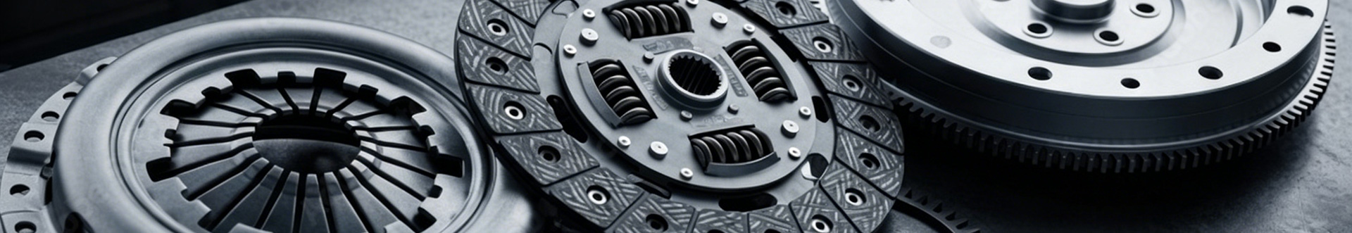
What steps to follow when replacing clutch disc and pressure plate?
2026-06-16Replacing clutch disc and pressure plate is a systematic overhaul task that requires standardized disassembly, inspection, cleaning, centering installation and post-replacement adjustment. Skipping any procedure will lead to clutch slip, shudder, incomplete separation and rapid re-wear. The complete operation workflow is divided into pre-work preparation, disassembly, component inspection, assembly installation, auxiliary parts fitting and final commissioning.
Step 1: Preparation and vehicle fixing
Park the vehicle on flat, solid ground, engage the handbrake fully and place wheel chocks to prevent rolling. Lift the vehicle with a professional hydraulic jack and secure it firmly on safety support stands; never work under the vehicle supported only by a jack. Drain small amounts of transmission oil to avoid leakage during gearbox removal. Prepare special tools including clutch alignment mandrel, torque wrench, cross screwdrivers, socket sets, degreaser and lint-free clean rags. Check new clutch disc and pressure plate for complete specifications, intact friction linings and undamaged diaphragm springs before disassembly.
Step 2: Disassemble relevant connecting components
Disconnect the negative battery terminal to avoid short circuits. Remove the clutch shift linkage, hydraulic clutch pipeline or pull cable, and label each connector for accurate reinstallation. Take off the starter motor fixed on the transmission bell housing, then detach all bolts connecting the gearbox to the engine block. Support the transmission case with a transmission jack to bear its weight, and pull the gearbox horizontally backward to separate the input shaft from the clutch assembly. Take care not to tilt the gearbox violently to prevent bending the clutch release fork and scratching friction surfaces.
Step 3: Dismount old clutch assembly and clean the flywheel
After exposing the clutch cover assembly, mark the matching position of the pressure plate and flywheel for reference. Loosen pressure plate fixing bolts diagonally and gradually to release spring preload evenly, preventing sudden spring rebound and component deformation. Take down the old pressure plate and worn clutch disc by hand. Thoroughly clean the flywheel friction plane with degreaser to eliminate oil stains, carbon deposits and metal abrasive dust. Inspect the flywheel for deep scoring, thermal ablation cracks and warpage; resurface or replace the flywheel if defects exist. Clean the inner cavity of the clutch bell housing to remove lining fragments and metal debris.
Step 4: Full inspection of old and new clutch parts
Check the removed old clutch disc for lining wear limit, rivet exposure, burnt carbonization and broken hub torsion springs. Examine the old pressure plate for surface hot spots, uneven wear, cracked or deformed diaphragm spring fingers. For new spare parts, strictly avoid touching friction surfaces with greasy hands. Apply a tiny amount of high-temperature anti-seize grease only on the inner splines of the new clutch disc hub, then wipe excess grease to stop centrifugal splashing onto friction planes at high speed. Inspect the release bearing, pilot bearing and clutch fork for jamming, abnormal noise or abrasion; replace these wearing parts synchronously during clutch replacement to avoid secondary disassembly.
Step 5: Centering installation of new clutch disc and pressure plate
Insert the dedicated clutch alignment mandrel through the clutch disc spline hub, and insert the mandrel tip into the flywheel pilot bearing hole to fix the disc in the absolute central parallel position. Hold the disc tightly against the flywheel to prevent tilting or offset. Cover the new pressure plate assembly over the disc, align all mounting holes, and screw on fixing bolts loosely by hand without cross-threading. Tighten bolts in diagonal cross sequence in two stages: first apply half of the factory specified torque, then reach the full standard torque in the second round. Cross multi-stage tightening eliminates residual stress and pressure plate warpage. Pull out the alignment mandrel after all bolts are fully torqued.
Step 6: Reinstall gearbox and matched auxiliary parts
Lift the gearbox with the transmission jack, align the input shaft splines with the clutch disc hub splines, and push the gearbox horizontally forward smoothly. Do not hammer the gearbox housing to force assembly, as impact will deform diaphragm springs. Tighten engine-transmission connecting bolts evenly, refill transmission oil to the standard liquid level, then reinstall the starter motor, clutch cable or hydraulic pipeline, and shift linkage. Lubricate the clutch fork pivot and release bearing contact position with high-temperature lithium grease, wiping away overflowing grease. Reconnect the vehicle battery negative terminal.
Step 7: Adjustment and road test after replacement
Adjust the clutch pedal free travel to the manufacturer’s technical standard value. Too small free travel causes persistent micro-sliding friction, while excessive free travel leads to incomplete separation and difficult gear shifting. Step and release the clutch pedal repeatedly dozens of times to confirm smooth travel without sticking or abnormal squeaking. Carry out a low-speed road test: test gear shifting to eliminate gear collision noise, perform uphill acceleration to check for clutch slip and burning odor, and observe whether obvious startup shudder occurs. If abnormal symptoms appear, disassemble and recheck centering, bolt torque and component flatness immediately.
In short, the standardized replacement sequence follows “lifting and disassembly → flywheel cleaning → parts inspection → centered torque assembly → gearbox refitting → clearance adjustment and road test”. Complete cleaning, precise centering and cross torque tightening are three core steps to guarantee long service life of new clutch disc and pressure plate.
References
APA 7th Edition
Li, H., Wang, L., & Zhang, Y. (2019). Thermal wear analysis of automotive clutch pressure plate and friction disc under frequent start-stop conditions. Journal of Engineering Materials and Technology, 141(4), 041008.
MLA 9th Edition
Li, Hao, et al. "Thermal Wear Analysis of Automotive Clutch Pressure Plate and Friction Disc Under Frequent Start-Stop Conditions." Journal of Engineering Materials and Technology, vol. 141, no. 4, 2019, p. 041008,
GB/T 7714-2015
[1] LI H, WANG L, ZHANG Y. Thermal wear analysis of automotive clutch pressure plate and friction disc under frequent start-stop conditions[J]. Journal of Engineering Materials and Technology, 2019, 141(4):041008.